Room 183: Icy Waters Early Rearing Room
![]()
This aquatic research room is set up inside an environmental chamber. The room itself is a stainless steel-lined Constant Temperature environmental chamber with air temperature control ranging between 5°C-30°C. This air temperature can be alarmed to ±1°C.
Animal Holding Room
Room: This room is a 40 m² environmental chamber. The walls, ceiling and fan units are stainless steel. The floor is a special hardened concrete to prevent water penetration. There is a grate covered trench located along the center of the room. The drain line for the tanks is located within this trench, as is a drain to the sanitary sewer.
The door for animal holding room and the anteroom has a covered window built into it to allow inspection of the room without entry. The door covering the window should remain closed at all times while not in use. There are no handles located in the anteroom.
To exit the animal holding room push on the left side of the door until it opens.
There are no catches to hold the door closed, only a mechanical door closure. There is provision to lock the door. If the door were to be locked while someone was still in the room, a release mechanism is located on the wall inside the room beside the door. Spin the knob until it comes completely off and push on the left side of the door until it opens.
Temperature control: Air temperature in the animal holding portion of the room ranges from 5°C - 25°C and is controlled by the Argus™ system. Temperatures are fully programable, the air temperature could follow a diurnal pattern, rising and dropping with the photoperiod. Temperature is monitored by a thermistor located within the room. The Air Temperature Deviation Alarm can be set to activate with as little as ± 1°C change.
Tanks: There are three 1.2 m tanks, equipped with dual internal stand pipes located in this room. The outer standpipe sits higher than the water level in the tank. Holes have been drilled through the bottom of this pipe to effect a self cleaning action for the bottom of the tank. Water is drawn through these holes and up over the inner standpipe. The inner pipe must still be briefly removed either every day or every few days depending upon internal load of fish, to clear waste build-up.
The nineteen 0.6 m tanks have cone shaped bottoms. A perforated PVC screen is placed over this cone to prevent fish from going down the drain. The tanks are designed to self clean. Waste drops through the PVC and is drawn down into the drain line. The cone shape acts to keep waste from settling in the tank. These tanks are also equipped with an external standpipe. The standpipe for these tanks must also be removed briefly either every day or every few days depending upon internal load of fish, to clear waste build-up.
Biofiltration: This room is not provided with biofilters.
Aeration: Low pressure air for tank aeration is supplied through black ABS pipe that circles the room. Air is supplied from three 1 hp Gast regenerative air blowers located in room 174.
Power: This room has five 115 V and two 220 V electrical circuits. There are two duplex receptacles per 115 V circuit. These are located around the perimeter of the room. Each circuit has a duplex ground fault receptacle. If power is lost to a receptacle, check the buttons located in the middle of the ground fault receptacles. If one is sticking out, press it back in to reset the power. If power is lost again, report it to Aqualab personnel. A circuit breaker panel is located on the wall in the anteroom. Please do not open this panel without proper authorization.
Lights: This room has a combination of fluorescent and incandescent lights in weatherproof fixtures. The room has a fully programmable photoperiod (i.e., the photoperiod can be programmed to emulate that found at any latitude in the world or any artificial photoperiod that the researcher requires). At “dawn” the incandescent bulbs slowly ramp up to full intensity, then the fluorescent lights turn on sequentially in three steps. At “dusk” the process reverses with the incandescent bulbs slowly ramping off at “sunset” Photoperiod is monitored by a light sensor located in each room. The Photoperiod Alarm is set to activate if the lights do not turn on or off as the program requires. The lights can be turned on manually from the Argus™ panel located in the hall outside Room 181. An alarm situation will occur if the lights are left on too long.
Anteroom
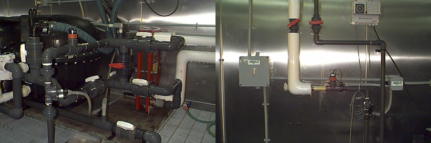
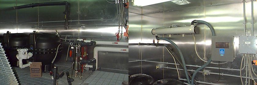
Room: The water treatment system is located in the anteroom and consists of a 2 m x 2 m x 1.5 m deep sump, two pumps, a sand filter with automatic backwash valve, a charcoal filter with manual backwash valve, a four bulb UV sterilizer and one plate heat exchanger.
The anteroom is also supplied with a sink with hot and cold domestic water, and cupboards above and below the sink for limited storage of chemicals and equipment. A fire extinguisher is located beside the door. Windows in the doors provide visual access to both rooms, the animal holding room door has a small door over the window.
To exit the anteroom push on the left side of the door until it opens.
There are no catches to hold the door closed, only a mechanical door closure. There is provision to lock the door. If the door were to be locked while someone was still in the room, a release mechanism is located on the wall inside the room beside the door. Spin the knob until it comes completely off and push on the left side of the door until it opens.
Water Temperature Control: Water temperature is controlled and monitored by the Argus™ system and consists of one plate heat exchanger supplied with hot or cold glycol. Water temperature is monitored going in and out of the exchanger by thermistors located in the pipes. These thermistors are set to activate an alarm (Water Temperature Deviation Alarm) if the water temperature deviates from the target temperature by a preset margin.
The computer control system regulates the position of two two-position three-way actuated valves to provide either hot or cold glycol. An actuated modulating valve regulates the amount of glycol supplied to the heat exchanger to maintain the target water temperature. The range of water temperatures in this room is approximately 3°C - 25°C. There is a small amount of flexibility in the system, which is governed by the flow rate of water through the exchanger and the surface area of the plates found in the exchanger itself. The Aqualab has spare plates to increase the capacity of the exchanger if the need arises. Water temperature in this room is set for 3°C.
Water Replacement: Water is added to the room’s recirculation system on a regular basis. The volume added is controlled by the Argus™ system which in turn controls the make-up water solenoid valve. The make-up water system is composed of a paddlewheel flow sensor and a solenoid valve on a 1" PVC supply line . Water is fed directly from Aqualab’s pre-filtration system into the room’s sump pit. Unlike the other rooms water is added to replace a specific volume of water that is wasted by the system. Water in this room never overflows the sump pit standpipe. This water leaves from a 1" line, controlled by the outflow solenoid, that is fed directly from the recirculation system after UV sterilization. 10,000 L of water is bled out in pulses of 30 sec duration 675 times a day. The number of pulses per day is determined by the volume of water that passes the outflow paddlewheel flow sensor in 30 seconds.
Water Recirculation: Water is recirculated around the room from the sump pit to the tanks and back again. Two pumps, located in the pump pit, pump water through the sand filter, the charcoal filter, the UV sterilizer, and the plate heat exchangers. After the water is filtered and the temperature is modified, it travels to the tanks in the animal holding room. Water overflows stand pipes located within each tank and returns via drain lines to the sump pit. The drain lines are found in the trench. Each set of trays has a set of blade valves to direct flow either into the trench (for cleaning and disinfection) or back to the sump (for recirculation).
Recirculation water flow is monitored by a paddle wheel flow sensor which is set to activate an alarm when flow drops below a preset level (Low Flow Alarm). The preset level is dependent upon the minimum required water flow.
Pump Pit: A float switch is located near the bottom of the pump pit to indicate water accumulation in this pit. This switch will activate an alarm as soon as it is triggered (Flooded Pump Pit Alarm). This alarm’s purpose is to protect the pumps from immersion in the event of a leak into the pump pit.
System Water Volume: The water level in the sump pit is monitored by an air pressure level sensor. When the water level drops below a preset point the make-up water solenoid valve opens. Water is added until the sump is once again full. If the water level drops below 70 cm in depth an alarm is activated (Low Water Level Alarm) and the make-up water solenoid opens. If the water level drops past 30 cm, the pumps will be turned off by the control system, to protect them from burnout. This will activate another alarm (Low Flow Alarm). When the water level rises above 30 cm the control system will reactivate the pumps, thereby restoring flow. When the water level rises above 70 cm the Low Water Level Alarm will be deactivated.