Room 154: Undergraduate Marine Teaching Lab
This room is setup to house the undergraduate teaching collection of marine fish and invertebrates.
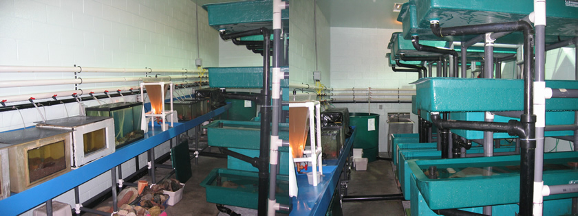
Room: The walls are epoxy coated concrete block and the floor is a specially hardened concrete to prevent water penetration. There is a grate covered trench located along the center of the room. The drain line for the tanks is located within this trench, as is a drain to the sanitary sewer.
Air temperature in this room is monitored, but is not under the Argus™ system’s control.
Tanks: There are seven 2.25 m long trays, four 1.5 m long tanks and four 2 m long tanks. These tanks are arranged into five banks. One bank is composed of 4 trays while the other four banks have one of each size tank (2.25 m tray on top, 1.5 m tank in the middle and the 2 m tank on the bottom). Each tank or tray is sullied with an internal standpipe. The room also has three 1.2 m diameter tanks complete with internal standpipes.
This room also has two twelve foot long wet tables that can be used to set aquaria on for small experiments. System water and low pressure air are available for the aquaria on these tables.
Biofiltration: The biofiltration for this room is accomplished in the gravel bed located in the sump pit in room 161. New biofilters need time to grow bacterial cultures. Nitrosomonas sp. grow first, converting ammonia to nitrite. There is a lag time before Nitrobacter sp. start to grow. It is during the time that Nitrobacter sp. is becoming established that elevated levels of nitrite could become dangerous to fish. Nitrobacter sp. converts nitrite to nitrate a much less toxic form of organic nitrogen.
Aeration: Low pressure air for tank aeration is supplied through black ABS pipe that circles the room. Air is supplied from three 1 hp Gast regenerative air blowers located in room 174.
Power:This room has five 115 V and two 250 V three phase electrical circuits. There are two duplex receptacles per 115 V circuit. These are located around the perimeter of the room. Each circuit has a duplex ground fault receptacle. If power is lost to a receptacle, check the buttons located in the middle of the ground fault receptacles. If one is sticking out, press it back in to reset the power. If power is lost again, report it to Aqualab personnel. A circuit breaker panel is located on the wall in the anteroom. Please do not open this panel without proper authorization.
Lights: Lighting in this room is provided by weatherproof incandescent fixtures. This room has a fully programmable photoperiod (i.e., the photoperiod can be programmed to emulate that found at any latitude in the world or any artificial photoperiod that the researcher requires). At “dawn” the incandescent bulbs slowly ramp up in intensity, and at “dusk” they slowly dim. The time required to ramp to full intensity and the final intensity of the lights is programmable. The Photoperiod Alarm is set to activate if the lights do not turn on or off as the program requires. The lights can be turned on manually from the Argus™ panel located in the hall. An alarm situation will occur if the lights are left on manual for too long.
There are also 3 growth lights suspended from the ceiling over the top trays. These lights are also photoperiod controlled and turn on and off, after and before the light ramping sequence.
Recirculation system: Located on the east wall are three pipes, these pipes supply the room with recirculated water of three different temperatures. The recirculation system can be found in room 161 and is composed of a 600V March pump, a PRA rotating screen filter, a gravel bed filter, a Trojan 2 bulb UV sterilizer and three Armstrong plate heat exchangers. The system is controlled by Argus™. Water is not added automatically to this system, if water is lost Aqualab personnel must be notified. To understand more of the function of this system see the section on room 161.
Control System: Argus™ controls and monitors the pump, the make-up water supply, the water temperature, the room’s photoperiod and four receptacles located on the east and west walls of the room.
Flow: The system has three paddlewheel flow sensors, one on each water supply line, that are monitored and alarmed. The pump has a temperature sensor located on the output to monitor and protect from overheating caused by cavitation.
Make-up water: A paddlewheel flow sensor is integral to the make-up water system. An ultrasonic level sensor is used to maintain and monitor water level in the sump pit.
Water Temperature: Each heat exchanger has a temperature sensor used to control, monitor and alarm water temperature.
Photoperiod: A photosensor is located within the room to monitor light operation.
This room has 4 controlled receptacles that can be used to program on/off function for variety of equipment. Currently two of these circuits are in use to control the overhead growth lights. The room also has installed in it a set of controlled extension cords, these cords are located on the west wall over the wet bench to provide the same on/off programmability as the wall receptacles. Also located within this box is wiring to provide sensor input for student experiments.
To understand more of the function of each system see the section on room 161.