Room 184: Noranda Environmental Toxicology Room
Animal Holding Room
Room: The walls are epoxy coated concrete block and the floor is a specially hardened concrete to prevent water penetration. There is a grate covered trench located along the center of the room. The drain line for the tanks is located within this trench, as is a drain to the sanitary sewer.
Air temperature in this room is monitored, but is not under the Argus™ system’s control.
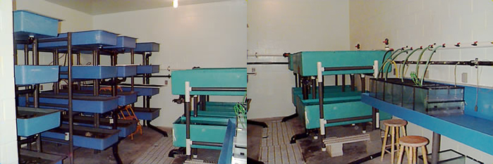
Tanks: There are sixteen 1.2 m long tanks arranged in racks of four tanks each, each tank has an internal standpipe. There are also six 1.5 m long tanks arranged in banks two tanks high, each with internal standpipes. Two of these tanks have double standpipes such that they can have the temperature modified external from the main recirculation system.
Biofiltration: The biofiltration in this room is accomplished in the gravel bed located in the sump pit. New biofilters need time to grow bacterial cultures. Nitrosomonas sp. grows first, converting ammonia to nitrite. There is a lag time before Nitrobacter sp. starts to grow. It is during the time that Nitrobacter sp. is becoming established that elevated levels of nitrite could become dangerous to fish. Nitrobacter sp. converts nitrite to nitrate a much less toxic form of organic nitrogen.
Aeration: Low pressure air for tank aeration is supplied through black ABS pipe that circles the room. Air is supplied from three 1 hp Gast regenerative air blowers located in room 174.
Power: This room has five 115 V and two 220 V electrical circuits. There are two duplex receptacles per 115 V circuit. These are located around the perimeter of the room. Each circuit has a duplex ground fault receptacle. If power is lost to a receptacle, check the buttons located in the middle of the ground fault receptacles. If one is sticking out, press it back in to reset the power. If power is lost again, report it to Aqualab personnel. A circuit breaker panel is located on the wall in the anteroom. Please do not open this panel without proper authorization.
Lights: Lighting in this room is provided by weatherproof incandescent fixtures. This room has a fully programmable photoperiod (i.e., the photoperiod can be programmed to emulate that found at any latitude in the world or any artificial photoperiod that the researcher requires). At “dawn” the incandescent bulbs slowly ramp up in intensity, and at “dusk” they slowly dim. The time required to ramp to full intensity and the final intensity of the lights is programmable. The Photoperiod Alarm is set to activate if the lights do not turn on or off as the program requires. The lights can be turned on manually from the Argus™ panel located in the hall. An alarm situation will occur if the lights are left on manual for too long.
Anteroom
Room: The water treatment system is located in the anteroom and consists of a 2 m x 2 m x 1.5 m deep sump, two pumps, a four bulb UV sterilizer and one plate heat exchanger.
The anteroom is also supplied with a sink with hot and cold domestic water, and cupboards above and below the sink for limited storage of chemicals and equipment. A fire extinguisher is located beside the door. Windows in the doors provide visual access to both rooms, the animal holding room door has a small door over the window.
Water Temperature Control: Water temperature is controlled and monitored by the Argus™ system and consists of one plate heat exchanger supplied with hot or cold glycol. Water temperature is monitored going in and out of the exchanger by thermistors located in the pipes. These thermistors are set to activate an alarm (Water Temperature Deviation Alarm) if the water temperature deviates from the target temperature by a preset margin.
The computer control system regulates the position of two two-position three-way actuated valves to provide either hot or cold glycol. An actuated modulating valve regulates the amount of glycol supplied to the heat exchanger to maintain the target water temperature. The range of water temperatures in this room is approximately 4°C - 25°C. There is a small amount of flexibility in the system, which is governed by the flow rate of water through the exchanger and the surface area of the plates found in the exchanger itself. The Aqualab has spare plates to increase the capacity of the exchanger if the need arises. Water temperature in this room is set for 13°C.
Water Replacement: Water is added to the room’s recirculation system on a regular basis. The volume added is controlled by the Argus™ system which in turn controls the make-up water solenoid valve. The make-up water system is composed of a paddlewheel flow sensor and a solenoid valve on a 1" PVC supply line . Water is fed directly from Aqualab’s pre-filtration system into the room’s sump pit. 50,000 L of water are added in pulses of one minute duration, 325 times a day. The number of pulses per day is determined by the volume of water that passes the paddlewheel flow sensor in one minute.
Water Recirculation: Water is recirculated around the room from the sump pit to the tanks and back again. Two pumps, located in the pump pit, draw water through a gravel bed filter located in the sump pit. Water is then pumped through the UV sterilizers, and the plate heat exchanger. After the water is filtered, sterilized and the temperature is modified, it travels to the tanks in the animal holding room. Water overflows stand pipes located either within the tank or beside it and returns via drain lines to the sump pit. The drain lines are found in the trench. Each 1.2 m tank and each set of 0.6 m tanks has a set of blade valves to direct flow either into the trench (for cleaning and disinfection) or back to the sump (for recirculation).
Recirculation water flow is monitored by a paddle wheel flow sensor which is set to activate an alarm when flow drops below a preset level (Low Flow Alarm). The preset level is dependent upon the minimum required water flow.
Pump Pit: A float switch is located near the bottom of the pump pit to indicate water accumulation in this pit. This switch will activate an alarm as soon as it is triggered (Flooded Pump Pit Alarm). This alarm’s purpose is to protect the pumps from immersion in the event of a leak into the pump pit.
System Water Volume: The water level in the sump pit is monitored by an air pressure level sensor. When the water level drops below a preset point the make-up water solenoid valve opens. Water is added until the sump is once again full. If the water level drops below 70 cm in depth an alarm is activated (Low Water Level Alarm) and the make-up water solenoid opens. If the water level drops past 30 cm, the pumps will be turned off by the control system, to protect them from burnout. This will activate another alarm (Low Flow Alarm). When the water level rises above 30 cm the control system will reactivate the pumps, thereby restoring flow. When the water level rises above 70 cm the Low Water Level Alarm will be deactivated.