Room 161: Recirculation System Mechanical Room
Access to this room is restricted to authorized personnel only.
Room: The water treatment systems for rooms 150, 152 and 154 are located in this room. Each system consists of a 2m x 2m x 2 m deep sump with a gravel bed filter, a screen filter, one pump, one two bulb UV sterilizer and three plate heat exchangers.
A fire extinguisher is located beside the door.
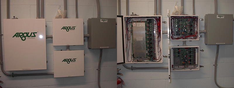
Water Temperature Control: Water temperature is controlled and monitored by the Argus™ system and consists of three plate heat exchangers supplied with hot or cold glycol. Water temperature is monitored going in and out of the exchangers by thermistors located in the pipes. These thermistors are set to activate an alarm (Water Temperature Deviation Alarm) if the water temperature deviates from the target temperature by a preset margin.
The computer control system regulates the position of two two-position three-way actuated valves to provide either hot or cold glycol. Actuated modulating valves regulate the amount of glycol supplied to each heat exchanger to maintain the target water temperatures. The range of water temperatures in this room is approximately 4°C - 25°C. The range of temperatures between heat exchangers for this room is restricted to the ΔT for the exchanger. The exchanger must be able to change the water from the mixed water temperature found within the sump to the set point in a single pass. Therefore the system can only handle temperature differences between heat exchangers of 3 - 4°C (e.g. 8°C, 12°C, 16°C). There is a small amount of flexibility in the system, which is governed by the flow rate of water through the exchanger and the surface area of the plates found in the exchanger itself.
Water Recirculation: Water is recirculated around the room from the sump pit to the tanks and back again. Water enters the room and passes though a rotating screen filter before dropping into the sump pit. The pump, located beside the heat exchangers, draws water down through a gravel bed filter, which acts as a biofilter, then pumps it through the UV sterilizer and the plate heat exchangers. After the water is filtered and the temperature is modified, it travels to the tanks in the animal holding room. Water overflows stand pipes located either within the tank or beside it and returns via drain lines to the sump pit. The drain lines are found in the trench. Each large tank or each set of smaller tanks or trays has a set of blade valves to direct flow either into the trench (for cleaning and disinfection) or back to the sump (for recirculation).
Recirculation water flow is monitored by a paddle wheel flow sensors, on each water line, which are set to activate an alarm when flow drops below a preset level (Low Flow Alarm). The preset level is dependent upon the minimum required water flow.
Biofiltration: Each system within this room is provided with biofilteration. The biofilter is located in the gravel bed filter in the sump pit. New biofilters need time to grow bacterial cultures. Nitrosomonas sp. grows first, converting ammonia to nitrite. There is a lag time before Nitrobacter sp. starts to grow. It is during the time that Nitrobacter sp. is becoming established that elevated levels of nitrite could become dangerous to fish. Nitrobacter sp. converts nitrite to nitrate a much less toxic form of organic nitrogen.
System Water Volume: The water level in each sump pit is monitored by an ultrasonic level sensor. When the water level drops below a preset point the make-up water solenoid valve opens. Water is added until the sump is once again full. If the water level drops below a preset level (setpoint 1) an alarm is activated (Low Water Level Alarm) and the make-up water solenoid opens. If the water level continues to drop past another prest level (setpoint 2), the pump will be turned off by the control system, to protect it from overheating and draining the sump pit. This will activate another alarm (No Flow Alarm). When the water level rises above the preset point (setpoint 2) the control system will reactivate the pump, thereby restoring flow. With the resumption of flow the No Flow Alarm will be deactivated. When the water level rises above first preset point (setpoint 1) the Low Water Level Alarm will be deactivated.
Water Replacement: Raw water (untreated water) is added to each room’s recirculation system on a regular basis. The make-up water system is composed of a paddlewheel flow sensor and a solenoid valve on a 1" PVC supply line . The volume added is controlled by the Argus™ system which in turn controls the make-up water solenoid valve. Raw water is fed directly from Aqualab’s pre-filtration system into the room’s sump pit. The number of pulses per day is determined by the volume of water that passes the paddlewheel flow sensor in one minute. Volume to be added is fully programmable and ranges from a few litres to tens of thousands of litres per day. Raw water flow into the pit for room 154 is alarmed immediately. Salt Water: Salt water is made up in room 174 in the marine water mixing tanks and is pumped to the pit. Salt water is added manually to the pit for room 154.