Room 180: Falconbridge Thermal Effects Research Room

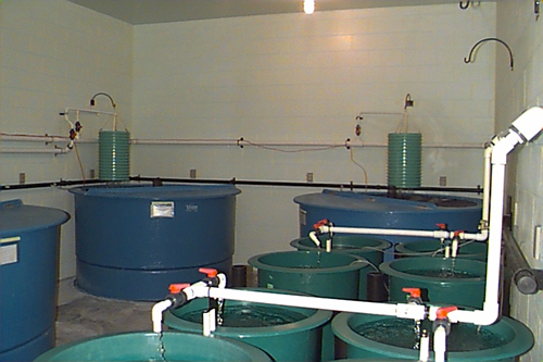
This aquatic research room has three 1.8 m diameter fiberglass tanks and eight 0.6 m fiberglass diameter tanks located within the holding area. This room is designed to facilitate the study of aquatic thermal effects by providing up to three separate water temperatures.
Animal Holding Room
Room: The walls are epoxy coated concrete block and the floor is a specially hardened concrete to prevent water penetration. There is a grate covered trench located along the center of the room. The drain line for the tanks is located within this trench, as is a drain to the sanitary sewer. Air temperature in this room is monitored, but is not under the Argus™ system’s control.
Tanks: The 1.8 m tanks are equipped with dual stand pipes. The external standpipe sits higher than the water level in the tank. Holes have been drilled through the bottom of this pipe to effect a self cleaning action for the bottom of the tank. Water is drawn through these holes and up over the internal standpipe. The internal pipe must still be briefly removed either every day or every few days depending upon internal load of fish, to clear waste build-up. The 0.6 m tanks have a cone shaped bottom, a perforated PVC screen is placed over this cone. The tanks are designed to self clean. Waste drops through the PVC and is drawn down into the drain line. The cone shape acts to keep the wastes from settling in the tank. These tanks are also equipped with an external standpipe. The standpipe for these tanks must also be removed briefly either every day or every few days depending upon internal load of fish, to clear waste build-up.
Biofiltration: This room is provided with biofilters. The biofilters are located between the inflow lines and the 1.8m tanks. They are made of green ribbed PVC pipe with a perforated PVC screen on the bottom. Number ½ and 2 plastic Tri-packs™ fill the pipe. New biofilters need time to grow bacterial cultures. Nitrosomonas sp. grows first, converting ammonia to nitrite. There is a lag time before Nitrobacter sp. starts to grow. It is during the time that Nitrobacter sp. is becoming established that elevated levels of nitrite could become dangerous to fish. Nitrobacter sp. converts nitrite to nitrate a much less toxic form of organic nitrogen. Biofilters should not be allowed to dry out. This is particularly important in marine systems, dry-out will result in sterilization of the biofilter.
Aeration: Low pressure air for tank aeration is supplied through black ABS pipe that circles the room. Air is supplied from three 1 hp Gast regenerative air blowers located in room 174.
Power: Each room has five 115 V electrical circuits. These are located around the perimeter of the room. Each has a duplex ground fault receptacle. A circuit breaker panel is located on the south wall inside the anteroom. Please do not open this panel without proper authorization.
Lights: Lighting in this room is provided by weatherproof incandescent fixtures. This room has a fully programmable photoperiod (i.e., the photoperiod can be programmed to emulate that found at any latitude in the world or any artificial photoperiod that the researcher requires). At “dawn” the incandescent bulbs slowly ramp up in intensity, and at “dusk” they slowly dim. The time required to ramp to full intensity and the final intensity of the lights is programmable. The Photoperiod Alarm is set to activate if the lights do not turn on or off as the program requires. The lights can be turned on manually from the Argus™ panel located in the hall. An alarm situation will occur if the lights are left on manual for too long.
Anteroom
Room: The water treatment system is located in the anteroom and consists of a 2 m x 2 m x 1.5 m deep sump, two pumps, a sand filter with automatic backwash valve, a charcoal filter with manual backwash valve, a four bulb UV sterilizer and three plate heat exchangers. Water supplied to each of the 1.8 m tanks in this room first passes over a biofilter to convert ammonia to nitrate. The anteroom is also supplied with a sink with hot and cold domestic water, and cupboards above and below the sink for limited storage of chemicals and equipment. A fire extinguisher is located beside the door. Windows in the doors provide visual access to both rooms, the animal holding room door has a small door over the window.
Water Temperature Control: Water temperature is controlled and monitored by the Argus™ system and consists of three plate heat exchangers supplied with hot or cold glycol. Water temperature is monitored going in and out of the exchangers by thermistors located in the pipes. These thermistors are set to activate an alarm (Water Temperature Deviation Alarm) if the water temperature deviates from the target temperature by a preset margin.
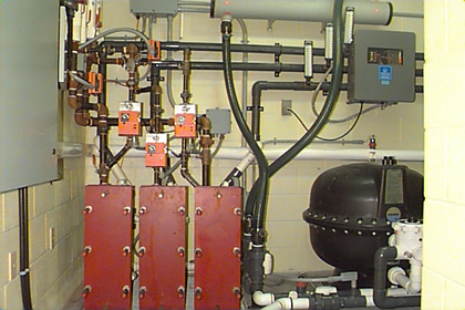
The computer control system regulates the position of two two-position three-way actuated valves to provide either hot or cold glycol. Actuated modulating valves regulate the amount of glycol supplied to each heat exchanger to maintain the target water temperatures. The range of water temperatures in this room is approximately 4°C - 25°C. The range of temperatures between heat exchangers for this room is restricted to the )T for the exchanger. The exchanger must be able to change the water from the mixed water temperature found within the sump to the set point in a single pass. Therefore the system can only handle temperature differences between heat exchangers of 3 - 4°C (e.g. 10°C, 13°C, 16°C). There is a small amount of flexibility in the system, which is governed by the flow rate of water through the exchanger and the surface area of the plates found in the exchanger itself. The Aqualab has spare plates to increase the capacity of the exchangers if the need arises.
Water Replacement: Water is added to the room’s recirculation system on a regular basis. The volume added is controlled by the Argus™ system which in turn controls the make-up water solenoid valve. The make-up water system is composed of a paddlewheel flow sensor and a solenoid valve on a 1" PVC supply line . Water is fed directly from Aqualab’s pre-filtration system into the room’s sump pit. 30,000 L of water are added in pulses of one minute duration 216 times a day. The number of pulses per day is determined by the volume of water that passes the paddlewheel flow sensor in one minute.
Water Recirculation: Water is recirculated around the room from the sump pit to the tanks and back again. Two pumps, located in the pump pit, pump water through the sand filter, the charcoal filter, the UV sterilizer, and the plate heat exchangers. After the water is filtered and the temperature is modified, it travels to the tanks in the animal holding room. Water overflows stand pipes located either within the tank or beside it and returns via drain lines to the sump pit. The drain lines are found in the trench. Each 1.8 m tank or each set of four 0.6 m tanks has a set of blade valves to direct flow either into the trench (for cleaning and disinfection) or back to the sump (for recirculation). Recirculation water flow is monitored by a paddle wheel flow sensor which is set to activate an alarm when flow drops below a preset level (Low Flow Alarm). The preset level is dependent upon the minimum required water flow.
Pump Pit: A float switch is located near the bottom of the pump pit to indicate water accumulation in this pit. This switch will activate an alarm as soon as it is triggered (Flooded Pump Pit Alarm). This alarm’s purpose is to protect the pumps from immersion in the event of a leak into the pump pit.
System Water Volume: The water level in the sump pit is monitored by an air pressure level sensor. When the water level drops below a preset point the make-up water solenoid valve opens. Water is added until the sump is once again full. If the water level drops below 70 cm in depth an alarm is activated (Low Water Level Alarm) and the make-up water solenoid opens. If the water level drops past 30 cm, the pumps will be turned off by the control system, to protect them from burnout. This will activate another alarm (Low Flow Alarm). When the water level rises above 30 cm the control system will reactivate the pumps, thereby restoring flow. When the water level rises above 70 cm the Low Water Level Alarm will be deactivated.